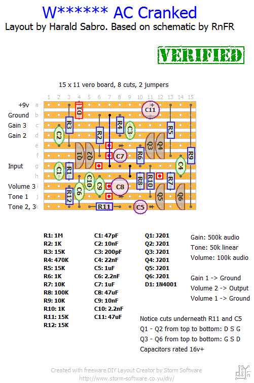
Threw this one together last night. Not yet verified, but I’m hoping you’ll let me know if you give it a try.
Update (25.09.2011): The layout is now verified. Thanks to Hookey.
Update (09.10.2012): I was asked to refrain from using the company and product names, so layout has been updated accordingly.


Assuming the board gets the correct voltage, the first thing that springs to mind is one or more faulty transistors. You could try swapping in the ones from your earlier build and see if it makes any difference? Or maybe try 2N5457 instead?
I built this pedal a few years ago and it sounds great. I recently decided to build another one and it sounds awful. When you strum lightly it sounds almost clean but if you strum a little harder it almost buzzes. I’ve rebuilt it six times and put it on a circuit board and I get the same sound. Tried new components, biased it to 4.5-4.7 every build, went over all solder joints on each build and made sure everything was in the right place. I thought it might have been the solder, because I started using a new brand of solder (Bernzomatic Electronic Silver Bearing Rosin Core Solder Lead Free), but I tried lead/tin solder and it did the same thing. I am at a complete loss. This one has me stumped. I know this build works I’ve built it before and recently breadboarded it to test it. Any help would be great.
Gudday Harald,
Built this, worked great first go. I find it a bit bassy though, hat would I change to get rid of a bit of the woofyness?
Having said that, it does the Queen thing quite well.
Thanks for letting us know, Simon. Always appreciated 🙂
Hi Harald and everyone else. Thanks for the layout! I can say this is working and you can verify it. I built it and it worked on the first try. I owned one in the past and I can safely say it sounds like the original. Sorry if this is 3 years too late lol.
Check out the FAQ section on JFET biasing. You have two choices; either experimenting with R3, R5 and R9 to find the correct biasing value (or replace with trimpots if you can fit them), or keep trying different JFETs until you find ones that bias correctly with the resistors you’ve already got.
Hi Harald, I’ve built again this pedal, but this time the sound is gated, and it’s different if I strum hardly or softly. The drain voltage of q1-q4 is about 0,80V, and q5-q6 voltage is about 3volt (something less actually). What to do? It’s only a J201 problem? Do I have to buy another set of them? (the couples drains are matched, but they seem solo low!) Thanks man 🙂
Well, it was indeed the power supply! Tested with a battery and the pedal is silent, and performs as i’d expect.
Odd really, and I think the reason I overlooked it is because I use the same power supply to power 5-6 of my other pedals, via a daisy chain. It is totally silent on those, and some of those are higher gain too, the Triple Wreck, Riot and so on.
I suppose this may convince me to purchase a good quality supply. I’ve made enough nice pedals now to warrant it.
Thanks again Harald, superb site, my favourite.
Regards
Ian
I’m no authority on the theory behind all this so this is just a hunch. Could the noise be coming from the power supply? What happens if you replace your DC adapter with a battery?
Hi, I hope someone can help! I’ve recently built this pedal but i’m having problems with noise. The effect seems to be working but there is a lot of background noise, so much that the pedal is unusable. I’ve thoroughly checked the layout, links, cuts in the board etc, but this one has me stumped.
I thought it might be the transistors, biasing etc but I have about 15 J201’s available, but all seem the same. Regarding the biasing, i’m unsure of how best to do this. What I did was insert one J201 at a time, and check the drain voltage. When I had two that were close, I inserted them both. This resulted in a drain voltage of approx 3.5v when measured from either J201. Is this correct? I have also tried pairing transistors so that the drain voltage with both in together measures, around 4.5v, but got the same noise.
I have an audio probe and start to get this noise as soon as I probe the signal off the first transistor pair drain legs. The noise is further amplified once I hit the second and third pairs of J201’s.
Could this be a duff component, or is there something I am missing? I have confirmed all resistor and capacitor values are correct, and double checked all of the pots and wiring.
Bit stumped here, as it seems like the transistor is the problem as the noise happens so early on in the signal path. Hoping someone can help! Excellent site, and up to this point numerous successful builds.
Ian
Just built this one too… I didn’t expect it to be way more powerful than the PlexiDrive!! 😀 Is it “normal”? It has a lot of gain, like a beast! I’ve noticed the tone control is not so wide-ranged, but it works 🙂 Thanks Sabro!!!
I agree. If you look at the preamp emulators you’ll see an example of this. But since this based on a pedal that’s being produced in large numbers it makes sense for the producer to consider cost, assembly time and reliability. The trim pots cost a lot more, requires an extra setup step during production and you also risk a customer opening up the unit and twisting those trimmers to see what they do and invariably “break” the pedal.
I’ve kept the layout according to the schematic hence no trimmers, but I agree they’d be a lot easier to work with.
so “biasing” these j201’s seems like an important part of the build right? I honestly, absolutely hate working with those inline sockets (i wish someone would make better quality ones… I think they’re fine for a few component switches, then they get loose, I have them fall out all the time and make terrible contact)… anyways, it seems like it would be easier to temporarily install trimpots (or permanently) instead of the resistors connecting drain to ve+… right? I mean would that give just as good of results as using 15k resistors and adjusting jfets to get the proper voltage off the drain?
eh?
i made a pcb layout with diy layout creator here is the link : http://www.mediafire.com/?rc96vzxnty57swx I also added the .diy file and pcb .pdf file
PLEASE, CHECK BEFORE ETCHİNG İT !
Thanks Herald!
Always happy to fuel someone’s addiction! But seriously, happy to hear you figured it out and got it working properly.
Thanks for the info. I did a test on the pins and it was at about 2.4 so a few resistor changes to the bias and all is well. Over the last month Ive built your layouts for the Wooly Mammoth and Phase 90 with zero debugging needed and this one is the same. Absolutely nothing to do with the layout at all. Thanks so much for posting these and adding to my severe pedal addiction I have. Starting your layout for the Vibrotrem this weekend. Looks good and thanks again for the layouts and the advice on biasing.
Hi, Mark. You probably don’t have a dud, it’s just that those JFETs can vary quite a bit and you just need to find the right ones.
This circuit is a bit special in that each gain stage consists of two transistors in parallel rather than just one. All your JFETs require a drain voltage of approx. 4.5v-5.5v, and you have a few ways of achieving this. You will need to mix and match until you have reasonably close pairs of JFETs, and once you have this the drain voltage of each pair can be adjusted by increasing or decreasing the drain resistor (the resistor connecting the drain of each pair to +v). The easiest solution would be to just buy a whole bunch of JFETs and try them all until you have reasonably good pairs without touching the drain resistors.
Good luck 🙂
I did this build and it works like a champ. I have 1 issue with this thats not as a result of the layout but just cant pinpoint. When I fired it up, the gain was extremely low and seemed semi gated. My first thought is one of the j201. I removed Q1 and the volume and gain came back to life and is usable. However when the gain is between 10 and 2 its still semi gated but only on sustaining a note toward the end. I know I need to put the a j201 back in the socket but is it possible I just have a dud. WHen I put Q1 it back in the socket it has the issues. When I take it out, it is 99% useable. The layout is correct and all values are correct. Im sure its a very simple solution. Its a great pedal and thanks for this layout.
Congratulations on your finished build!
I use “diy layout creator” version 1, a piece of software written by a guy called Bancika. His website is called diy-fever; I’ve got a link on the right hand side somewhere.
Finished! This is a very nice sounding pedal. Lots of gain on tap.
Thanks for all the layouts! Do you use some kind of software to come up with these layouts?
I would definitely think as a pair.
Harald
Kind of a noob question. I built the plexi-drive recently and swapped J201s and tested the voltages on the drains until each one was in the correct range ( 4.5 – 5 ) for optimal sound.
I have built the cranked ac and am trying to do the same thing for the J201s in this circuit. The question is, do I test them for the voltage as a pair or individually. I ask because they seem to change voltage when I test them individually and then add the second of the pair ( the parallel wired J201s ).
Thanks
Given the size of the vero board I’d say it should fit comfortably in a 1590B.
As for the site options I’m not much help. I suppose you could subscribe to site updates via RSS. You’ll get notified when I add posts, but I don’t think you’ll get them when I update older posts though (I find this a bit annoying myself).
Its verified! Excellent! I would love to hear how it sounds? Does it fit in a 1590b?
Can we see some pics?
Also is there an option to click to receive notifications when someone replies and when you do a new post?
Thanks again for all your hard work dude!
Still not verified, sorry.
Is this thing still not verified? I would try it to verify it but I am such a noob if something was off I wh=ould probably not be able to give any corrections.
There’s a dedicated thread with schematic over at http://www.freestompboxes.org
Thanks again! Do you have a schematic for it too?