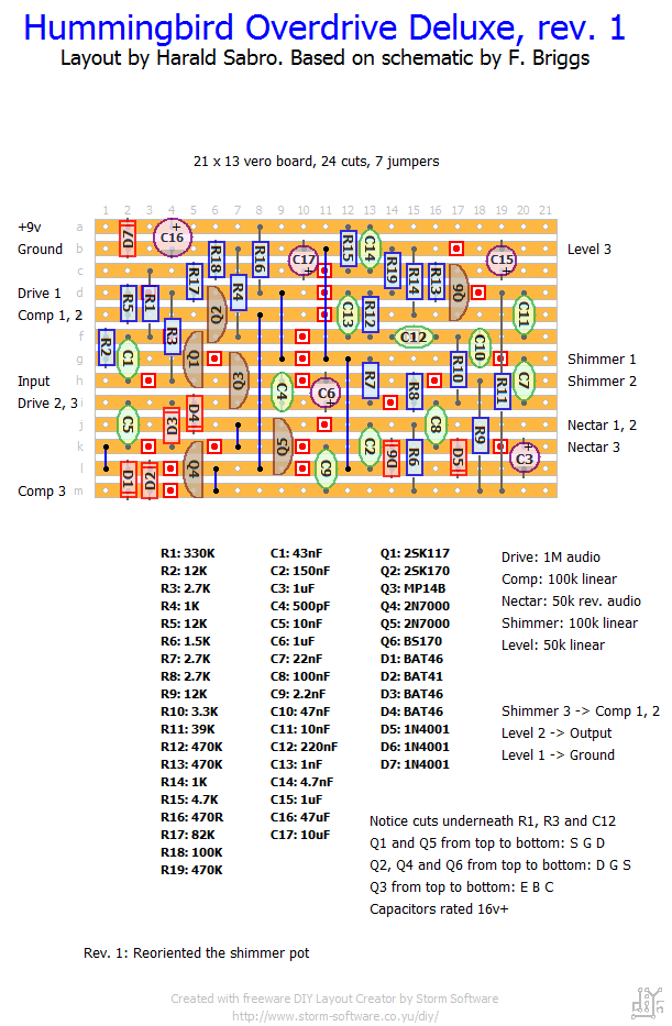
This one piqued my interest for some reason. I’m unsure about a few things and I’ve done a couple of assumptions so keeping my fingers crossed. I will try building this as soon as I’m able to source all the parts.
Most of the pots may have to be reoriented. I’m assuming the 2N7000’s are used as diodes as this was a bit unclear on the schematic. And I haven’t been able to figure out the pinout of the MP14B germanium transistor.
Update (02.02.2012): Built this tonight and I’m very pleased with how it sounds! Reoriented the shimmer pot, but kept everything else as it was. Verified.
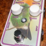
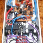
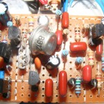
Update (08.04.2012): Boxed this one quite a while back, but didn’t get around to taking pictures until now. Notice how I squeezed that germanium transistor in there. Not very pretty… Will have to account for the bulkier size next time I try to fit one of those on a 1590B build. Effect sounds really nice, though! (Couldn’t resist the urge to put a hummingbird on there, making it quite silly and quite cool).


Nice link Harald, thanks. Have to look into that!
Haha, thanks. It’s actually transparency film. It’s all according to this great tutorial by frequencycentral over at FSB: http://www.freestompboxes.org/viewtopic.php?f=47&t=6145
And I use a 3M spray mount adhesive for fixing the graphics to the enclosure prior to coating it.
Harald, that enclosure looks great. I assume it’s a waterslide decal? I can’t get them to print out nearly that clearly…any tips on settings for the printer? I feel that I’ve experimented with everything and not come up with anything nearly that cool…in fact I’ve all but given up trying to put any kind of picture on. Any suggestions?
I haven’t heard anything more about the Mojo Cake. Maybe I should build one and see for myself…
Yes, thank you it made sense, so ramble on 🙂
Do you also know if someone solved the problems that occurred with the mojo cake.
By the way, I really really like this site 🙂
As a rough estimation we can break the useful range of capacitance into three segments; the pico-, the nano- and the micro farad range. Typically you use ceramic capacitors for pico, film for nano and electrolytics for micro.
In the nano range you’re pretty much stuck with film capacitors, but they’re also the ones that come in most flavors. Nobody agrees on what the better ones are and I think they all sound more or less the same in most cases.
In the pico range you’ll normally use ceramic disk capacitors, but you have the option of using mica/silver mica instead, though they’re more expensive and physically larger. Again, I’m not sure I can hear any difference in most cases.
In the micro range you’ll typically use electrolytic capacitors, although you have the option of upgrading to tantalum electrolytics. They’re more expensive and more sensitive to heat, but supposedly sound better in some cases. Also worth noting is that tantalums often marks (+) rather than the (-) you normally see on regular electrolytics.
Did any of that make sense or am I just rambling?
How do you choose which capacitors are silver mica or which metal film. And which resistors carbon or metal film? Or are there some crucial components were the material gives you an audible difference?
Thx
Excellent, thanks RnFR.
Thank you very much for your input, Briggs. Highly appreciated. I’m looking forward to giving this circuit a try myself.
MP14B is CBE.
Hi there, the 2n7000’s are used as clipping diodes – they affect the full frequency range of the signal, the BAT diodes act as clipping for the high-mids and treble and they are controlled via the “comp” pot (the higher the comp setting the more treble is clipped). You can use near enough any pnp transistor (Ge or silicon) and sub in values for the other strange stuff. I was playing with a lot of old russian components when I originally designed this, that’s why there are some strange values on there.
Some of the pots are pretty subtle in what they change, they could be internalised as trim pots to save on space on an actual build (the Shimmer and Compression controls could easily be done away with as trim pots in a sort of “set and forget” manner – i.e you set it to how you like it and then just leave it and don’t really ever need to change it with your gear!). I built it with all the pots on as even a subtle tweak can add a different dimension to the sound of the pedal depending on what other gear and amp you are using..
Hehe, that’s great. What about the orientation of the pots? Did you have to change any of them?
I used a regular pnp germanium transistor and both 2n7000’s and bs170s for the all of the fet transistors. I also ony used one kind of shotkey diode of which Im not sure what it was and my pedal works. Some of the pots dont really change the sound that much but Id say the vero is verified. It is a cool sounding low gain overdrive with some nice reaction to the dynamics of my playing.