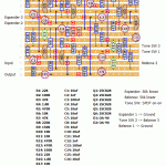
Based this on a schematic I found on FSB of unknown origin utilizing the 2SC828 transistor (notice pinout on this one). I found another schematic as well using 2N2222s and slightly different resistor values, but chose to go with the 2SC828 one. Here’s to hoping it checks out!
Oh, and I’m pretty sure this’ll fit in a 1590B enclosure 🙂
Update (10.11.2012): Built this one myself tonight. I didn’t have any 2SC828 transistors, but used 2N2222’s with no problems (just watch the pinouts, had to bend the legs a bit), so I can happily say that this works.


Incidentally I just posted a WIIO layout too. What are the odds…
Thanks Harald Ill give it a go once Ive finished trying to get a Ivark catalinbread WIIO to work Im struggling with veroboard in terms of bridging etc but Ill just keep trying.Still a newbie at this.
This one’s for you, Peter. Built the Super-Fuzz tonight and my build works 🙂 Give it a try! But if you choose to use a more common C B E transistor type do remember to bend the legs to match the 2SC828 pinout required on the layout.
Thanks ,Harald hopefully the circuit has no faults I dont think I could solve them, Id have to try Guitar Fx Layouts version a try otherwise.
Not sure anyone has verified this one yet. Let me do a little checking in the comments archive. I might just have missed it, wouldn’t be the first time.
Hi Harald I know you been asked this but has anyone verified this yet ,Ive made cuts to a board but dont want to add components till I think it will work??
Bummer! Thanks for giving it a try, though. Afraid I can’t really do much about this circuit right now, but will try to build it myself eventually.
Just put this one together. Used C828 transistors, and mostly the exact part values (a few ohms up or down on a couple resistors) and it is to my great regret to say it doesn’t work. I checked everything and it seems connected fine, I’ll triple check in the morning but I can’t seem to spot an error at first glimpse.
Hi Jimi. Nobody has attempted this one yet, so not yet verified.
I’d be very happy if you did 😀
hey harald, has this been verified yet? i looked thru the thread, just curious…
thanks bro
pink jimi
If you want to be safe and you don’t want to get into how the circuit works etc. you can’t go wrong with replacing each leg of the trim pot with a wire to the respective lug on your external pot. At best one of the wires will be unnecessary, but you can live with that.
Rangemaster is noted.
…at all! Definitely clear 🙂
Doing a sum with what you’ve (kindly) explained to me also on the fuzz face post – then correct me if I’m going wrong – it seems to understand that the general rule for adding an external pot as variable resistor it’s enough to wire the center lug and one of the outside lugs of the external pot in the place of the resistor on the board – no need to wire directly the two lugs between them.
About the replacement of the SPDT switch with a 3PDT footswitch, for some reason I figured that it required something more epic. Typical of the newbies… 😉
Thank you really a lot for the info, Harold, you’re great!
Will we ever benefit a Dallas Rangemaster layout – perhaps a point-to-point one and with a tone pot? 😀
– Your typical 3PDT foot switch is in fact on-on, so you can do a straight substitute using just one of the three poles in the 3PDT (i.e. lugs 1, 2, 3). Consequently you can get away with using an SPDT foot switch, or if you also want to include an indicator LED for the octave/tone mode you need a DPDT variant (i.e. 2 poles; 1, 2, 3, 4, 5, 6).
– There’s no reason you can’t replace a resistor or a voltage divider (two resistors in series between +v and ground) with a pot, but in this case it’s rather a question of what resistor(s) to replace. I had a quick look through the document and couldn’t say straight away where that trim pot is sitting in the circuit. If you do figure out which one(s) it is, if it’s just one resistor you replace it with one side of the pot (e.g. lugs #1 and #2), and if it’s a voltage divider you replace each resistor with either side of the pot (i.e. one resistor is replaced by lugs #1 and #2, and the other resistor is replaced with lugs #2 and #3).
Hope I didn’t confuse you more with my attempt at explaining things.
…a newbie question: how to wire a second 3PDT footswitch for the octave mode instead of the on/on switch?
More: is there a way to wire an additional external pot as variable resistor for the octave control, as described (albeit in form of internal trimmer) here – pag. 19?
http://buildyourownclone.com/leedsinstructions.pdf
Many thanks from Italy! 🙂
That one is almost identical to the one I based my layout on. The are a few minor differences, but nothing critical; I have C3 = 1n, C13 = 1n, I don’t have R1 and R10, and I have OA-90s instead of OA-91s (and of course the 2N2222s).
Try 2N2222A. I have no trouble finding the datasheet.
Think I found it… is this the one?
http://i1085.photobucket.com/albums/j436/Bross-ta-man/superfuzz.png
Have you got a link to the 2n2222 schem? I can’t seem to find anything with google. I haven’t got any 828s and I fancy breadboarding it.
You’re welcome! 🙂 Now let me know how it turns out.
Awesome, thank you Harald. I’ll make this bad boy a priority build! Thanks again buddy!!