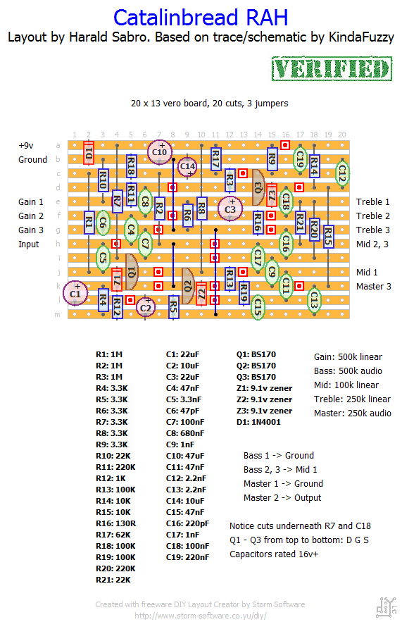
I’ve had a lot of requests for this one lately, and it was just traced out over at FSB so here’s a vero layout for it. I have no idea what this sounds like, but based on the hype it’s pretty good.
Update (30.04.2012): Layout now verified as working. Thank you Derek!


تابلو بر صنعتی
玩镰刀
Thanks so much for this schematics.
This one sounds so much better than any of my other overdrive pedals
Hi Leon,
I’m not sure I understand what you mean by running a ground wire from input to “Master” ground. You shouldn’t hear anything at all at ground potential. Have you wired it up as per the true-bypass diagram in the “Wiring” section?
If you think it’s the wiring you can try to simplify this a bit for testing purposes:
– Wire the pots (remember the extra connections listed in the lower right-hand part of the layout).
– Wire the DC power jack.
– Wire the input and output jacks (remember to ground the sleeves too).
– Make sure all ground connections are tied together (DC jack, input and output jacks, circuit board ground, “Bass 1” and “Master 1”).
You’ve basically hard-wired it in active mode. If this works it’s your 3PDT wiring.
Another great tool for debugging is the audio probe (there’s a link in the “debugging” section I believe).
Hope you figure it out!
Hi Harold,
I have build the CatalinBread. In de by-pass mode my guitar plays without problems.
If I switch the effect on, i hear no sound. If I run a ground wire from the input jack to the ground of the Master (250k Log, I hear a guitarsound for 0,5 seconds. Than the sound stops. I Have to release the ground connection and repeat the connection again to hear another 0,5 seconds of tone. It is like a light indicator.
I posted a photo on http://www.newtone-online.nl/forum/index.php/topic,7298.msg60635.html#msg60635
I think it’s a wire problem, but can’t find it.
Can you help me?
Léon
Cool! 🙂
Just want to say thank you Harald for making the layout available – I’ve tried it and it fired up no problems at all. Thanks!!!
Great news, Daniel 🙂
Yes Harald, maybe im too “overhyped” by this one 🙂
But anyway, my last attempt seems to solve the problem… i´ve bypassed R4 with a .022 cap, and its brings the pedal back to life! …dont know if my board have some issue with the C1 and R4 at input, but my “mod” solved the muffled sound issue… in the end, im not disappointed with the pedal, because its a really dynamic overdrive… and have a sort of “3D” sound… as if the natural sound of the guitar is mixed with the overdrive signal in a very good way… not a simple “blend” of the signal like a “sparkle drive” does. Very thanks for inspiring newbies pedal builders like me!
Happy to hear you’re getting somewhere, Daniel. The last issue, have you compared your build to the various demo videos out there and made sure this isn’t how the effect is supposed to sound? Not sure where you’d go from there.
After Check again an again, finally i´ve found my silly error! Wrong C8 value… it was 0.068uf in mine… seems that this cap has a major infuence over the drive freq. in fact the WIIO has a .47uf in place and sound a little more “gainy” and sharper… i didnt make an A/B test but a switch to this cap could be a nice mod for have a sort of “Zep / Who” mode.
But i still have an last “issue” with this one… i just would like to have more hi-fi, crisp high freq response… the sound is not bad, but mine sounds like the pedal have a sort of built-in cab simulation when put aside with my other drives… maybe i have another cap with wrong value… some suggestions?
Alright Daniel. Hope you’re able to sort it out!
Sry Harald, I´ve misspelled the BS170 as “fets”… i used all parts exactly the same as in your layout… Searching in another foruns, i´ve found that some builders have similar results… i´ll try to source the BS170 from othe brands to see if its the cause… Thanks again!
Hi Daniel,
You should be using MOSFETs for this one, not regular FETs. The BS170 is an N type enhancement MOSFET and I’m guessing you want something similar if you’re not using the exact part.
I haven’t built this myself and can’t comment on how it is supposed to sound. Regarding the disparity with overdrive compared to demos, have you considered things like input signal from different types of pickups etc.?
Hope you’re able to figure it out (check out the debugging section for some tips that might be useful).
Hi Harald, i wonder if the FETs are very critical on this one… i built mine and iim having some little issues… its only sounding really “overdriven” with the gain pot maxed.. i dont have the original to compare, but in the demos it seems to have more gain… also the treble pot have much less influence than the other two eq controls (again, dont kow if its the normal behavior of the circuit) and mine is not reacting very well to guitar´s volume pot as expected… i ve checked every component, ext. wiring and even knifed the board… everything looks fine. If you or someone else have some directions i would be very thankful… Anyway, thanks for the amazing layouts!
hey Harald, big sry!! for messung up such an obvious connection *self-smack*
ok, after renewing the BS170s i was able to get it working, but! (i also read your section for failures) i got a problem: im playing on a LM6100 with 2×12 1936 (105W). hitting my TS-808, every channel volume needs to stand at 9 o’clock, while master is at 9 o’clock, too, before im getting a headache and deaf ears in my small room.ok , so far…but with the DIY RAH-pedal, i need in clean channel, 100% volume and 100% master (INCREDIBLE SETTING!!) to drown the strings plek sound when im playing (to hear the distorted sound from the boxes!),i changed the transistor mounting twice, …my speaker box would have already flown away with this power output…. what could be the problem? Anyone else knows something like that? help me 🙁
Hi Rory,
I appreciate the feedback, but I’m fairly certain row “m” is a problem here. Take a closer look at the layout and you’ll notice row “b”, the “ground” row, is connected with row “m” through two jumpers, one from b8 to g8 and then one from g11 to m11. If your build isn’t working I suggest reading over the “debugging” section for a few tips on where to start.
Good luck 🙂
DUDE!! i worked with this plan, built my own layer, and it didn’t work! Im too unskilled.. NO 😛
i looked up this schematics
http://2.bp.blogspot.com/-bnlTjGc7DfM/T7zg-zA9OPI/AAAAAAAABW8/fXwHxSufzww/s1600/catalinbread+rah.PNG
U FORGOT TO MARK LINE “M” WITH GROUND!! (the buttom one)
plz fix it!
anyway, im going to work again…hopefully it should work now xP
Hi supro,
You’re not going to get a trim pot on there easily. They take up 3×3 board space and you’d also have to reroute several components/tracks etc. to make it work. One option would be to replace one of the pots with a fixed resistor; you can replace the Mid with a 50k resistor (mid permanently at 12 o’clock) but you have to squeeze the resistor in somewhere between the “Mid 1” and the “Mid 2, 3” tracks (before the trace cuts obviously). The bass pot will be slightly easier to replace by running a resistor from J17 to M17, and I guess an A500k pot at 12 o’clock will be about 100k.
Hi, I’d like to build this in a 1590a. I put many circuits this size in those enclosures. However, I dont think i can fit 5 knobs. Would there be a way to make one of the pots an internal trimpot? Preferably the MID. If not that, the BASS.
All sorted mate…I often get the mrs to have a scan at it..she dont know much about it but of course can follow the layout diagram .anyway..she heated everything again and bingo..so like you mentioned..most likely a cold solder joint…Thanks for the reply..Tim
Go over everything with a sharp eye and double check. Common mistakes that even I do from time to time: missing trace cut, jumper or even component, a misplaced component (often one hole off), solder bridge or cold solder joint, wrong orientation of transistor/IC, missing board wire or off-board connection.
Hope you’re able to sort it out, Tim.
Hi Harald built this before with no problems but ive just built another but i cant get the bass mids and treble working…gain and vol work fine,,,ive checked the wiring ..all seems fine….knifed the board so no solder joins….any idea what else to check
That`s what i thought too, compenent toleracnes, which could include the MOSFETS. The original has voltages close to 5.6v on the drains in all MOSFETS.. I`ll try to mees with the BIUAS resistors to match that and see what happens..
Not sure to be honest, but it may of course be component tolerances and such. Maybe there are differences between the manufacturers of the MOSFETs?
I built this version and A/B with an original. Seemed to be the original had more gain and the mids were more focussed while my version seemed to have more little headroom, little less gain and sound a little brighter overall. I was wondering if the MOSFETS could be the cause for the differences in gain. Are these sensitive to biasing like Jfets such as J201? Maybe I should measure the drains on the original and match mine. What do you think Harald?
you need humbuckers to be wound on the hot side to get an exact match (don`t know if this was the case on the demo i watched also) but deffo jimmy page tone. More a sort of mild overdrive using single coils. I did notice the gain pot wasn`t overly interactive, seemed to clean up very quickly, 100k pot gave a more subtle change, but you only want this for the JP tone so crank it up and leave it be, if need be use your guitar volume to clean up.
Thanks for verifying, Derek! 🙂
Verified, circuit works fine, will plug in some humbuckers tomorrow and compare to demos of original. Thanks a lot for another great layout Harald. Kudos dude 🙂
It’s a Jimmy Page pedal! Wtf, this layout went out this morning and I populated my plexi-drive vero yesterday night! XD Maybe I should build this one too? 😀