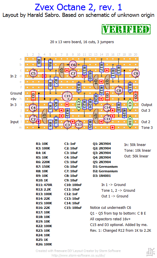
I’m taking a guess this is an octave fuzz of some kind. Let me know if this works and what you think of it 🙂
Update (11.11.2012): Built this one tonight and found, as was reported, that Q3/Q4 were slightly misbiased. I changed R12 from 1K to 2.2K according to another schematic and this solved it. There’s also the option of changing R17 from 10K to 4.7K instead, thanks to Mrlindell for that suggestion.


I use 24 AWG wire. I think that’s 0,5mm.
Thats ok harald 🙂 therse a life outside pedal building as well!
I dont know if you should update with my changes. But i do know from what i been reading that changing it back and changing r12 to 2k2 instead wont make a diference to how the transistors work. Beacuse that part of the circuit was wrong biased when it was 10k, you needed to change the voltage on the transistors collector in order to change bias. Try building it yourself and see if the schematic is wrong or if im wrong. If your build has the same problem with wrong voltage on q 3 and q4 we know that my change will work. Ok thanks
Of to next build think im gonna do a standard ts 808.
What sorta wire do you use? In mm if you know
I used an unsigned schematic I found in the octane 2 thread over at FSB. I double checked this now with madbean’s schematic and PCB layout and he still has R17 at 10k, but R12 is 2k2 and not 1k. So it’s probably down to an error on the schematic.
Not sure whether to update the layout with a 4k7 or a 2k2. Any chance you could give 10k/2k2 a try and report how it works? (I completely understand if you’re “done” with this build now 😉 )
Sorry I haven’t been around to answer you, not that I could have done this any better though. Great work getting it sorted. Will give this one a try myself and update the post/layout accordingly. Thanks!
Ok this one does now work. The circiut is not correct the q4 och q3 is not proberly biased. Iv changed r17 from 10k to 4,7k that makes the transistor work in range. But im not shure that the whole circuit is correct. Now it sounds like the original.
But i call this one sorta verified
Do you have the schematics you used to buikld the vero?? its hard to figure out what to change whitout it? But the circuit is not biased right. thats what makes it sorta gated sound
Ok it works but there are someting wrong!!!! my guess is that the voltage on transistors are of. What does the schematic say on voltage or can i just check data file for the 2n5088 and start cheking??
Ok harald this is verified. Wierd sounding fuzz though. Therse absolutly no sustain in tone. But its an great octavefuzz when playing highet up say 12 fret. I did not use your extra diod and cap.
But it sounds like the orginal. The problems i had must had been beacuse of cold solder joints and destroyed transistors.
The diod and capacitor that you added, what do they do? If taken away what happens to layout, will i have to put jumpers on those spots. I have a good feeling about the new vero i buildt 🙂
So frustrating! I’ll see if I soon can build this circuit myself. Maybe we can get to the bottom of this together.
Ok harald
Iv changed all the trasistors put them in sockets and so on. But the same problem as before, sorta! Now i can hear that the octave is there and sounding nice! But the pedal is on its sorta pumping, if i play hard on the guitar it works but the sound goes away quick, the tone doesent ring out, its like if you muted the guitar or turned down the volum realy quick.if i play easy no sound att all completly dead. Il give it one last chanse and rebuild my vero cause it sounds awsome. The diod and capacitor that you added, what do they do? If taken away what happens to layout, will i have to put jumpers on those spots. I realy want this to work!!
Ok thanks
Afraid I haven’t gotten that far on the theory yet. Maybe R.G. Keen’s debug pages over at http://www.geofex.com can be of help to get you started, though. There’s a section there on how to measure transistor voltages I believe.
Hi harald. Think iv found the problem. I tried it this morning with high volym on my guitar and it works but whith problems. The sound is sorta pumping fuzz. Iv hade this problem before on another pedal. I belive iv destroyed one or more transistors! I didnt have sockets for them so probely iv broken some of them with heat. What method sould i use to find out wich one is broken so i dont havde change them all. Think we will soone get this one verified.
Thanks
I will go over it tonight. Do you have any ideas were to start looking after i checked the usalll stuff? Since the signal gets through the circuit but sorta unaefected i guess it takes a pass through somewhere its not supposed to. It can not go through the in34a since its so clean. Iv never debugged something this advanced before so i would be glad for tips
Bye 🙂
Bummer! I don’t think anyone have tried this layout yet so it might also be the layout (or the schematic I based it on). You’re confident you’ve got the bypass wiring etc right and you’ve looked for obvious mistakes like solder bridges, cold solder joints, missing cuts, components and so on?
The radio frequencies you’re hearing is not an unusual problem, though, especially for high gain effects. For this try to keep wires short and perhaps even shielded from the input jack to the circuit input (via switch). But consider that this problem might be a side effect of the main problem of not having any effect at all. Might go away if you figure out how to make the circuit work.
Hi Harald
Iv buildt this during the week and im sorry to say i have problems. When the effect is on i get an unefected guittar sound
No fuzz and no octave but sorta clean guitar sound. Now to the funny part it allso pics up german radio wich i strange when i live in middel of sweden. Ive used 1n34a diods and im pretty shure my vero is correct. Any ideas??
Ok thanks