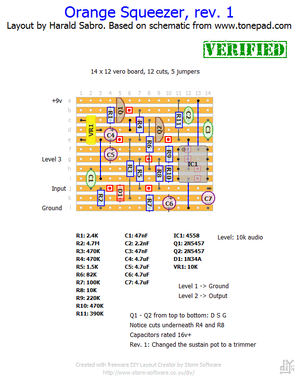
I did a layouts for the Orange Squeezer a good while ago and forgot about it.
Update (12.02.2013): So I finally had a look at this old layout tonight. I did change the Sustain pot to a trimmer instead, but that’s the only thing I did. Works nicely and sounds pretty cool even. Verified as working!


Well, they cost the same, don’t they? I say, why not!?
I know the original used a dual op-amp but why not just design it with a single op-amp, I have just designed one using a TL071. Otherwise we just have a wasted op-amp, i have no idea why Dan Armstrong would do this unless he had a spare 12000 dual op-amps laying around.
Just a question for the people who built and use it : is the quite important level loss on mine normal ? I use it with drum machine more than guitar and the low kick drum is really pumping so deep i need to amplify quite a lot after the orange squeezer !
Cheers
Just build this, second homemade pedal : excellent !
Thanks
Built this, but it distorted at first try. Replaced FET’s with lower Idss. Works now but the compression effect is not as big as I expected. Anyone else tried several FET’s ?
Yes, me too. Worked fine! We’re probably incredibly lucky the both of us 😉
Ive build this and it works fine. Maybe Im lucky? 😉
Cheers =)
Appreciate you taking the time to let me know, Bad Layout, whoever you may be. I’ll take a look at it.
There are several errors in this layout so it should not be considered verified.
To be honest I’ve never tried this circuit and I can’t really give you a good answer. I’ll put it on my figure-out list.
Hello 🙂
I have a little issue: when the sustain knob is at “0”, there is no sound. When I turn it up, until two-thirds of pot excursion there is no sound and there is a WHOOP as I turn the pot. Then it begins to work until the end of pot range, but the difference is very subtle… is everything ok or there’s something wrong? I tried to wire another 10k B pot but it was the same! Thanks 🙂
Thanks for the detailed write up, Josh. Sounds like a very useful mod.
I was confused about how it works. I assumed that the sustain knob controls compression so it should get quieter as you increase the knob. After I built it, I read up on how to set the sustain and found that your wiring is correct and I had reversed it. It should be silent at 0 and get louder as you increase the knob. Sorry for the confusion.
BTW, according to what I read, you should find the narrow range on the sustain pot where the volume increases dramatically. Useful settings are somewhere inside this band. I isolated this band by adding an arrangement of resistors to the pot lugs so that the useful range (which is less than 5% of the original sweep) now spreads over the whole sweep. It’s probably better to use an internal 10k trimmer (to roughly set the bias) and an external 1k or 2k pot (to set the sustain), but it was already boxed up and I didn’t see an obvious place to put the trimmer. A well-chosen resistor could replace the trimmer, but the value will depend on your trannies.
Within the useful range, it seems like you get more distortion as you increase the pot, and more attack as you decrease it. Thanks again. I love this thing.
Howdy. Just wanted to let you know I wired this up the way Joseph suggested and the sustain pot worked backwards for me. I then wired it up the way you have it laid out and it works great. Thanks for all the great layouts. I’m looking forward to trying some more. BTW, I used A10K for level and B10K for sustain so maybe that is the difference. Thanks again!
Mark
Very happy to hear this, Joseph 🙂
Hi Harald. I built this. It works great. My only mods were sending both Sustain 1 and 2 to ground (so compression increases clockwise), and replacing the 2.4k resistor with two 1.2k in series (I didn’t have any 2.4k). Sounds fantastic. Thanks very much.
BTW I tried connecting IC pins 4 and 5 to see if it made any difference. It didn’t.
This may be a mistake on my layout. It’ll give you a reverse pot, but nothing more severe than that.
Hi Harald. Thanks for all the layouts. This layout has Sustain 1 going to ground, and Sustain 2 and 3 connected. I have seen other layouts (Torchy’s and IvIark’s) with both Sustain 1 and 2 going to ground. Will this reverse the direction of the pot, or have any other result?
Just a thought: in the last week I’ve built two Zendrives from this fine site, and the Squeezer. Only one Zendrive worked out of the three circuits, and it was the one I happened to build right into the box without using my test rig. I just remembered hearing that some circuits need to actually be in the box with hardware mounted etc. to work for grounding reasons. Could that be my problem here, because the only one that did work I built right into the box, as I’ve done with all previous projects on this site.
I tried to build this and it didn’t work. I then started checking with my audio probe and discovered I got nothing at the input even after replacing the input wire and C1. At points beyond this I did get sound but no effect. Any ideas? I’m no expert at troubleshooting or any of this obviously, but I would expect to hear something with the audio probe at input I think. The testing is done on a test rig I built that is an enclosure with the off board wiring all done…I used star grounding. Looking at the diagram the only way I see it going to the IC is input to R2 jumping to the “L” strip, going to L12 and jumped up under the IC. But as you can see I’m grabbing at straws here. C1 (.047U) won’t allow anything to pass, so it’s hard to say whether it’s a problem with the input or the cap…if I had to suspect one I guess it would have to be the cap, but as I said I replaced that with the same result. I’ve cleaned out all the channels between the strips and cleaned the board with a tooth brush and alcohol. I’ve also re-flowed all the solder joints. Any ideas? I mainly did the project to try to verify, but it looks like others, while still having problems did better than me!
Thanks, Luka. Pin 5 shouldn’t have anything to say as far as I understand. I’ll see if I can put this together myself eventually. Maybe I’ll spot something wrong.
This was the layout: http://www.aronnelson.com/gallery/main.php?g2_view=core.DownloadItem&g2_itemId=39617&g2_serialNumber=1
Apparently, all I can see is the IC pin 5 going to ground as well as IC pin 4, that differs from your layout that is. I’ve only figured this out after rebuilding it so I haven’t tried connecting the pins on your layout, I’ll try leaving out the trace cut on a future build to see if that’s the cause of the clipping.
Cheers!
I had a second look at this and the layout seems to check out against both the tonepad and the ggg schematics. Can you link me the layout you mentioned?
Will have a second look at this. Thanks for the heads up.
Hey, just wanted to let you know that there might be a few errors on your Orange Squeezer vero. I’ve built it on your layout and got quite a bit of clipping, then tried another I found over at aronnelson, by Torchy I believe, with the same components and it worked like a charm. If you get the time you should revise it because this is a killer effect.
Cheers!