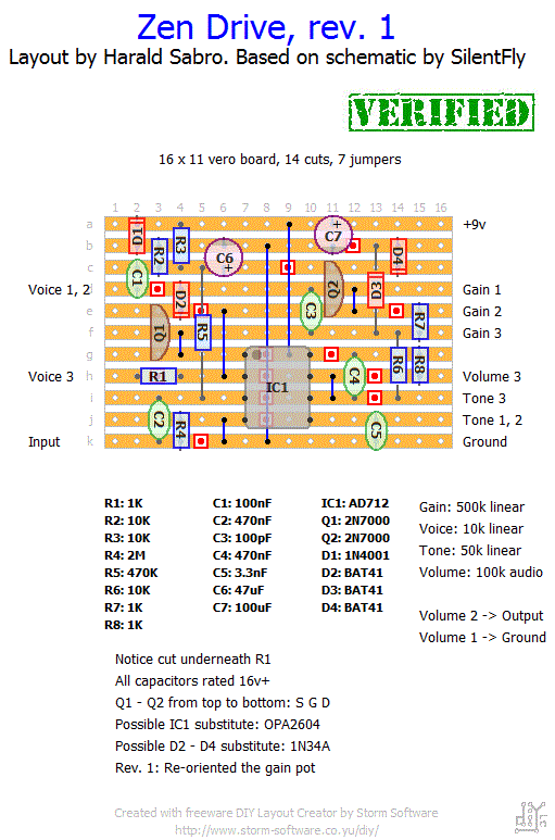
A nice little circuit that supposedly sounds really nice. Here’s a vero layout for the Zen Drive.
Update (17.10.2011): The OPA2604 IC reputedly sounds very nice in this circuit, thanks to Matt for the tip.
Update (31.12.2012): Updated layout with gain pot reversed. Thanks for not letting me forget, guys 😉


Ah! Thanks for reporting, Alec. Will give those a try.
Just to update. Since Lovepedal has started making these for Hermidia it has come to light that the correct chip is an NE5532 and D3 sould be germanium, probably a 1N34A. Sounds great!
Thanks for the suggestions, rabinnh 🙂
I made just a few changes, the first (to me) being the most important.
1) It sounded quite harsh and “trebly” to me, even with the tone all the way down, so I swapped out the tone pot from a 50K linear to a 100k linear, which gives it more versatility for cutting the highs.
2) For my purposes, I didn’t use switching jacks, just regular jacks and added an on/off toggle between the power supply and the board.
3) Wired in a 3PDT for a true bypass circuit.
4) I added a red LED with a 300 ohm resister between power and ground as a power led.
5) I added a green LED with a 300 ohm resister in parallel with the 3PDT to indicate when the circuit was engaged.
6) A minor change; I long ago stopped using batteries and use a 9v pedal board supply with chained plugs, so I didn’t install a battery clip, just a female 9v plug.
Wow duh! Ok thanks again for your help! Hopefully when I test out out next weekend it works!
Matthew, I assume you mean the voice pot and not the volume?
There’s an easier way to do it. The board label basically means you should connect this point to one or more lugs on a pot, but it only means they need to make an electrical connection. Instead of wiring two wires, one to each lug, you can connect one of the lugs with a wire from the board and then connect the two lugs together directly.
Last question as I should be finishing this build tomorrow. In instances where two wire go to one space such as from the board to the volume pot, I don’t have wire thin enough to easily thread two pieces into a hole. So for this I soldered on in the regular way and then I soldered the other wire from the opposite direction (so one lead was pointing up and one was pointing down). Will this work?
Thanks! Yes, that was very clear and helpful.
Matt, good question really. I assume you’re talking about the shared connection at the “k” strip? The two components are electrically connected through the strip it self, so more or less of a solder connection doesn’t change anything. It’s natural for joints next to each other on the same strip to flow into one another and become a single solder joint. That’s fine and mine end up that way all the time. As long as it’s not excessive and looks neat there’s no problem. Now, if we’re talking about bridging two solder joints across strips that’s not something you want to have (solder bridge).
Hope that made at least a little sense.
This may seem dumb, but when soldering this circuit on a veroboard, if you had two components soldered next to each other, such as R4 and C2, it would be bad to let the solder joints be connected by excess solder, correct?
A wonderful overdrive. Have used the AD712 with BAT 41s and BB 2134 with BAT432. Both excellent. Check out GuitarPCB.com for their take on the Zen, called the Zenith Drive. They’ve added a third clipping diode (RED LED), which is very interesting to hear. Makes the smooth even smoother.
YESSS, wonderful pedal!!! OPA2604 may cost more than other opamps, but I’ll have to try it out elsewhere too. Sounds great! However, I had to switch lug 1 and 3 on the gain pot to make it work clockwisely… whoops, when writing this I notice Rapadi’s comment of June 2011, so I guess it’s old news. I’ll press submit anyway to remind you it’s not fixed yet 🙂
I’ll put mine back on the table again and put the right AD712 in it. It sounds very fuzzy and high gain?
What can be wrong?
I am really not that thrilled about this little unit. I don’t like the way the notes decay and i think i have heard other mass market overdrives that are way more musical, imho. Maybe it’s because i used cheap bits and a JRC4558?
Haven’t tried it in a band setting yet, but it seems very nice.
But into my JD-10 it would be super.
Haha, we all do it. Good to hear you figured it out. How do you like the sound?
After i swapped the 4.7K Ohm resistor with the correct 470K Ohm, it works perfect!
Stupid mistake not to wear glasses……..
Mine lacks gain and power, and sound mufled. I used an JRC4558. Could it be that?
Just built it and it’s GREAT! Used the OPA2604 IC and 1N4148 diodes, as I read around the net that these diodes give a little more gain and add definition to bass!
Really really great pedal for THE blues and rock sound! Long live Dumble!!
Sounds like I may have to try one 🙂 As for the various diodes I think you should give it a try and let us know what you think!
This is my favorite overdrive pedal ever. it is just so totally natural and has a nice amount of gain on tap. Use silver mica for the 100pf and I used a burr brown opa2134a and bat41 diodes with outstanding results. This pedal is so good it makes me want to buy one from those guys… maybe I’ll buy the tube version. are there any other od pedals that use a similar clipping setup?
would it be worth it to put the bat41’s (or some of them) on a switch with 1n34as on the other side? do they get a good and different sound?
My favourite overdrive. Put it together last weekend. Sounds great.
Thanks for the update. I’ll see if I can change the wiring on the layout.
Nice. I did this, and it really acts like the original, but the gain pot is wired to the wrong way. 1 is 3 and 3 is 1.. I compared this to the original, and they where really similar. OK the zendrive pics radio waves REALLY EASILY, but you can minimize this by covering the PCB heavily with plastic spray, it worked for me. But that problem is for all zendrive users