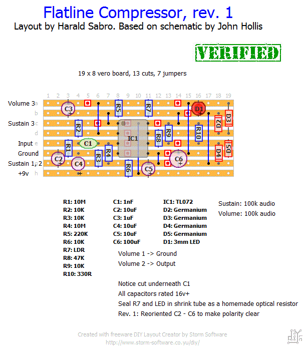
Here’s a new layout I’ve been working on over the holidays. The John Hollis’ “Flatline Compressor”.
Update (31.01.2011): Finished the Flatline layout today. I can confirm this one is working. Haven’t had time to play with it yet, though.
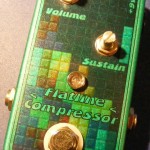
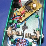
Update (18.05.2011): Boxed the Flatline compressor tonight. It sounds really nice, which somewhat makes up for the green enclosure turning out too dark for the transparent graphics. I tried a variety of different colored LEDs and found high brightness red and orange ones to work best, but your mileage may vary as this probably depends heavily on what LDR you use.
Update (20.10.2011): Fixed dead layout link.


I’m an idiot nevermind- Has anyone compared the homemade LDR thing to the VTL5c2 or 5c9? I found one site that preferred the vactrol, but he didnt seem to think the LDR sounded any good at all, so maybe he didnt get it right?
So the layout here does not mention the LDR- Got confused there for a minute when i found another source mentioning the LDR. How do you wire a Vactrol- I was gonna use the VTL5C2, unless the homemade LDR method is preffered. What do you guys think?
I just did this build today…I’m waiting for boxes, so it’s not boxed, but I set it up with my test rig and it’s phenomenal…it really adds a chunk before an overdrive, and it really lives up to the name flat liner, because it basically holds on at the same level longer than some others, yet still allows some dynamics through. I haven’t heard much about it, so I don’t know it that fits the proper description, however I’m really happy with it, and couldn’t stop playing! The little bit I used it clean it sounded like it might be a bit darker, more like the Ross.
I built this one, sounds great, I used a 3mm red LED (the normal cheap ones) and the smallest LDR that come in the radio shack variety pack they sell. Thanks for the great layouts!
Doesn’t matter, I dug out a fresh led and now it works perfectly.
Hey, I just finished this one, but the led in the optical resistor doesn’t light up at all. I used 1N4148 diodes rather than Germanium ones, do you think this could be the issue, or is it time to start debugging?
Haha, you’re right. Must have slipped in there by accident. I wouldn’t think it makes any difference though. Probably just redundant.
C5 (10uF) on your layout doesn’t seem to be on the original schematic. Why did you add that?
Btw, thanks for your awesome website! 😉
Ok thanks, I’ll try a few then
Keep the good job !
I actually don’t know. I bought two different kinds from smallbear and both worked fine. You could get one of each and find out which one you like most? The ones I got both have several Megs dark resistance, but I’m not sure how important that characteristic is. Sorry I can’t help you any more than this.
So I guess it’s what Musikding calls photo cells resistor.
In that case, which value should i use from this list ?
http://www.musikding.de/index.php/cat/c82_Photo-Cells.html
Thank you
Oups sorry, didn’t see your previous answer.
Thank you !
Did you have a look at the link I posted as a reply earlier? http://www.sabrodesign.com/?attachment_id=954
I used a cheap LDR (light dependent resistor) from smallbear, I think it was the 9200 version, and I used a high brightness, clear red 5mm LED. Wrapped them both up in a short piece of 6.4mm black shrink tube. Voila!
Hi, what do you mean by “homemade optical resistor” ?
Could you be a bit more specific ?
Thank you
Denis
I recently built this with ulyssees layout, great compressor. I used a red 3mm led
http://hownotomakeapedal.blogspot.com/2011/05/another-big-update-4-new-pedals.html