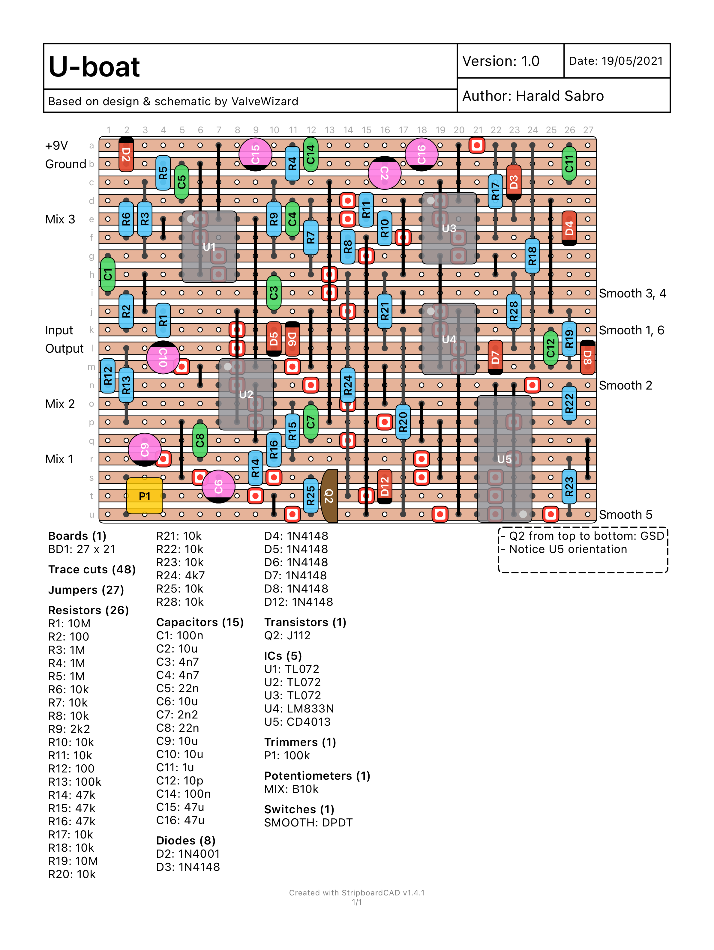
I was thinking about building an analog octave effect like the Boss OC-2, and decided to put together a layout for this interesting project. Not
Category: Effect

I’ve recently put together “my own” take on a VCA compressor. I put that in quotes because most of the design is straight from the
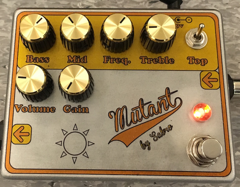
As with the Workhorse, I had some fun designing a PCB for the “mutant” circuit. Here are the results: Mutant
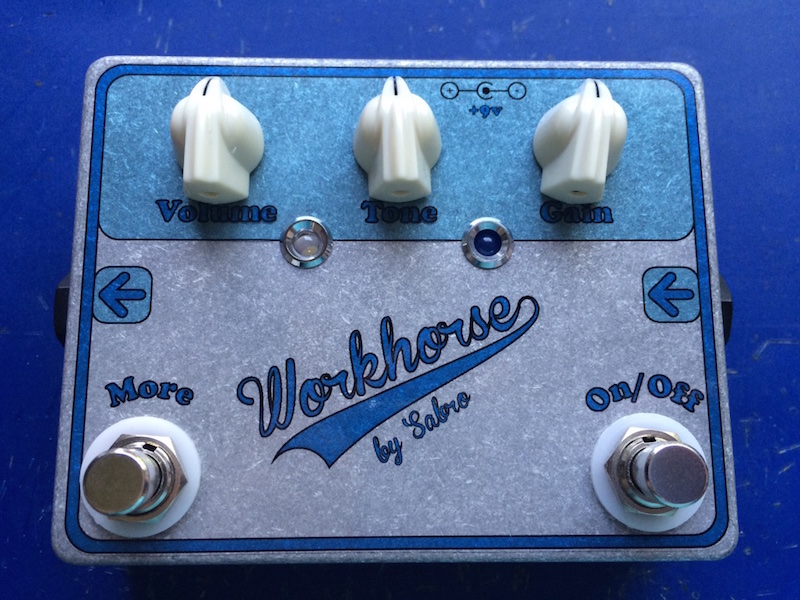
I’ve been tinkering with some PCB design lately. Here’s the results of my first project. Link: Workhorse
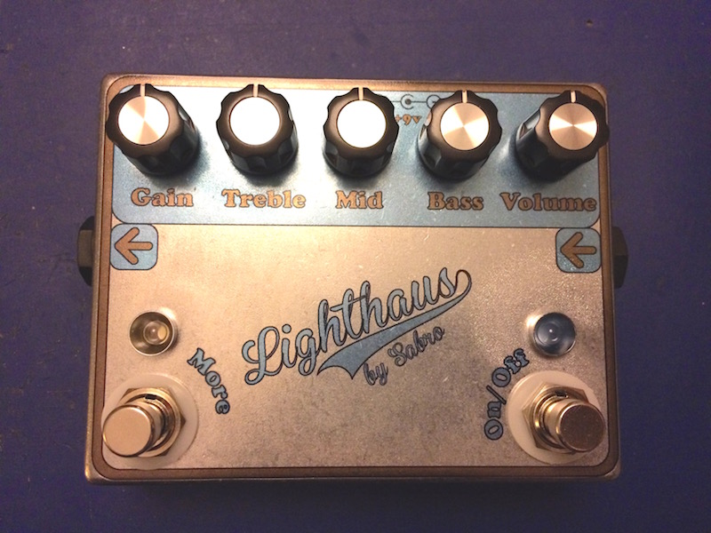
I’ve built another high-gain effect to address some of the short comings of the “Lighthaus” (mostly the issue of noise). I’m absolutely loving the result.
I’ve been doing some more cooking lately. This one is a rework of the Openhaus, which is way too big and costly to build for
Update (25.04.2016): The new version (v2) is up and running, and I’ll try to share as much as possible on github. Source code Pinout Example
Update (07.08.2015): This one is now verified as working, thanks to Patrick 🙂 Update (10.07.2014): Minor change to the schematic and vero layout adding a
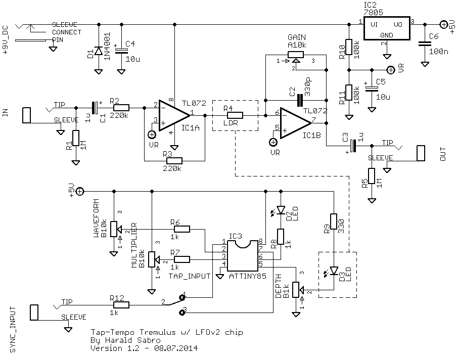
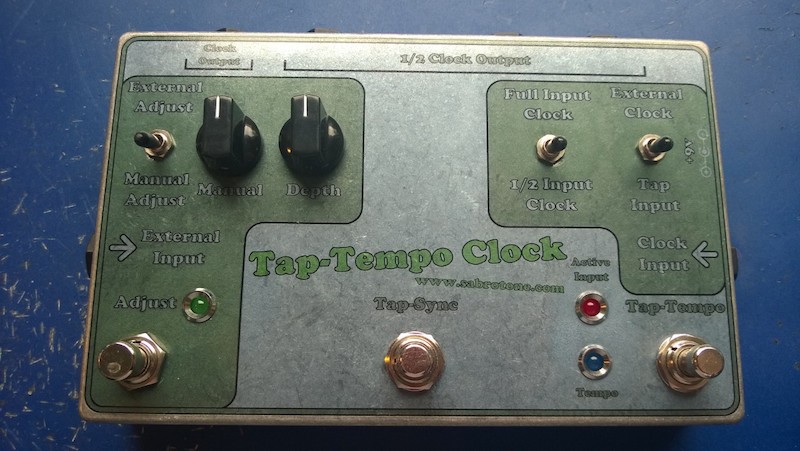
Update (10.07.2014): Minor changes to the schematic and vero layout to make this work with the tap-tempo clock project; tap input switch, series resistor and