Did this a few nights ago, but didn’t get around to posting it until now. Not yet verified, but I’m fairly confident it’s correct (assuming the excellent schematic drawn by Bajaman is correct, of course).
Update (11.10.2011): Verified thanks to Hookey.
Update (28.11.2011): Finished my own build tonight. I’m generally enthusiastic about compressors, but this one sounds even better than expected. Hah!
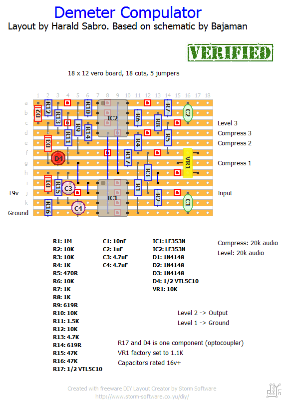


620ohm is just fine. Remember that most of these resistors have between 1% and 5% tolerance margin, so even a 1% metal film resistor of 619ohm can vary between ~613-625ohm
Hi Harald, I’ve used 620r resistors instead 619r. Is this resistor value so critical in this circuit?
Thank you for this fantastic site.
Luis
You most likely have a small mistake somewhere, something we all have to deal with. Start by looking at the “debugging” section and see if you can get some ideas. Did you use a VTL5C10 optocoupler?
My demeter no compress. sound clean and good. But no compress signal.
Why?
Great, mika 🙂
hi !!!
I’ve made it and it works fine !!!!!
some bug at the beginning,forgot a wire (from output jack to negative pole of battery)
best regards from france !!!!!!
mika
I have a opto vtl5c1 and Lf353 P, . First, i will change this.
Thanks
Hi alexy. Sorry to hear you’re having trouble.
Have you checked out the debugging section for tips and ideas?
I can’t say anything about other veros, but I’ve personally built this one following the layout here and mine works great. Did you use the right kind of optocoupler? I’m thinking there’s a small mistake somewhere and you just need to find and correct it.
Hello, I built a conpulator. The volume pot works, the signal sounds good, but compress the pot does nothing. I move from one side to another and not notice anything. I’ve checked and everything is ok.
I have seen other Vero and wiring is different. It may be that the failure?
I need help thanks
aah now i get it! Thanks!!
Hi Stappe,
Have you checked out the wiring section? I’ve got a few illustrations on how to do offboard-wiring; you probably one the regular true-bypass variant.
Hello,
I’ve managed to build the circuit. Due to little knowledge I do not know how to solder the jack in/out, DC in, potentiometers, etc. Could someone make a little schematic for me, or explain it to me? Would be great!
Kind regards
Hi Karth,
You -may- actually be able to squeeze it in a 1590A. A 12 row board would just fit, but of course there’s the question of also fitting the jacks, switch etc.
You have to show us if you manage to pull it off, of course 😉
I know it’s a long shot, but does the board fit inside a 1590A enclosure ? A compulator this small would be so great.
This is also my favorite compressor. Thanks for the layout!
Sorry to hear that, asaf. Did you check your battery? 😉
Anyway, you should start out with some debugging. Since it did work there are a good few things you can eliminate, like missing trace cuts, solder bridges and missing/wrong components. I suggest you start by making sure you’ve got a nice and healthy power source connected and then use your multimeter to measure the voltages on the ICs.
Well,
I’ve built it. Worked for a few hours and then started to lose volume whenever I turn it on. Now it has no sound at all when turned on. I have no idea where to start… 🙁
They decided to do it that way because there wasn’t a standard back then? It really doesn’t matter at all. If you’re aiming to use a positive tip power supply then go ahead and wire up your build this way, otherwise I suggest you wire it as negative tip which would make it more compatible with whatever else you choose to put on your pedal board when it comes to power. This way you don’t have to use a dedicated power supply just for your compulator.
Ok… but why does the original compulator has a positive tip?
Do you mean the power supply jack? If so it’s entirely up to you whether you choose to wire it with positive or negative tip, but I suggest you go with the negative tip since it’s the de facto standard on modern guitar effects.
The trimpot controls the compressor’s preamp gain. I was hoping that it controls the attack… oh well.
BTW, I’ve read that the original pedal has a positive tip. does this schematic also has a positive tip?
Can’t remember exactly what the trimmer does, but I think it just sets the operating point of the compression pot, and it’s not very useful as an adjustable control. Give it a try though 🙂
What does the trim-pot does? changes the attack?
Can I replace it for a potentiometer, and if so, do I need to use a linear one?
BTW great website, I’m going to build a few other projects as well
Harald
You may be right on the part values. I’ll have to look back through and re-check everything. I feel pretty certain that there are no shorts and I check and re-check as I go through my builds so I won’t have to do any backtracking. But, I may have subbed a value or two because of availability ( I definitely used 25k audio pots because I couldn’t find 20k pots at supplier. I also noticed that the schematic that I got at FSB had log pots instead of audio – maybe that would affect the sweet spots ). I may do a rebuild and just make sure everything is exact.
Looking at that Fetto for my next build – had never heard of it but the clips I found sound great!
Thanks again. This site was a major find!
Hi, Tinker. I haven’t gotten around to building this one myself yet, so I’ve got very limited experience with this circuit. It sounds like it’s not working quite as it should, but rather than trying different op amp and vactrol options have you checked and made sure you’ve got all the components right, there’s no shorts etc?
Harald
Thanks for all the great layouts. I built the zendrive and it worked perfectly! I built the compulator and I’m not sure if it I have done something wrong. It works but I have to turn the volume/level almost all the way up to have the same volume as when the effect is off. The compression is very subtle compared to my old boss compressors – I guess the opto circuits are different by nature but on the clips of the original that I have heard, the effect is very pronounced and squashed even with the controls only halfway up.
I have tried swapping the opamps – no change. I swapped the vactrol for a spare that I ordered – less compression and still have to keep level most of the way up when I turn the compression anywhere above noon. Do you think this is a vactrol issue? I read that they are notoriously inconsistent.
Ahahah I just have to build soooo many fx I don’t know which one to begin with!
You’re welcome 🙂 Let me know how it turns out.
That’s just GREAT!
For Gilmour-tone lovers like me, this IS the compressor to build! Thanks so much! (I found a vero layout in the past, but it wasn’t “satisfying”!) 🙂