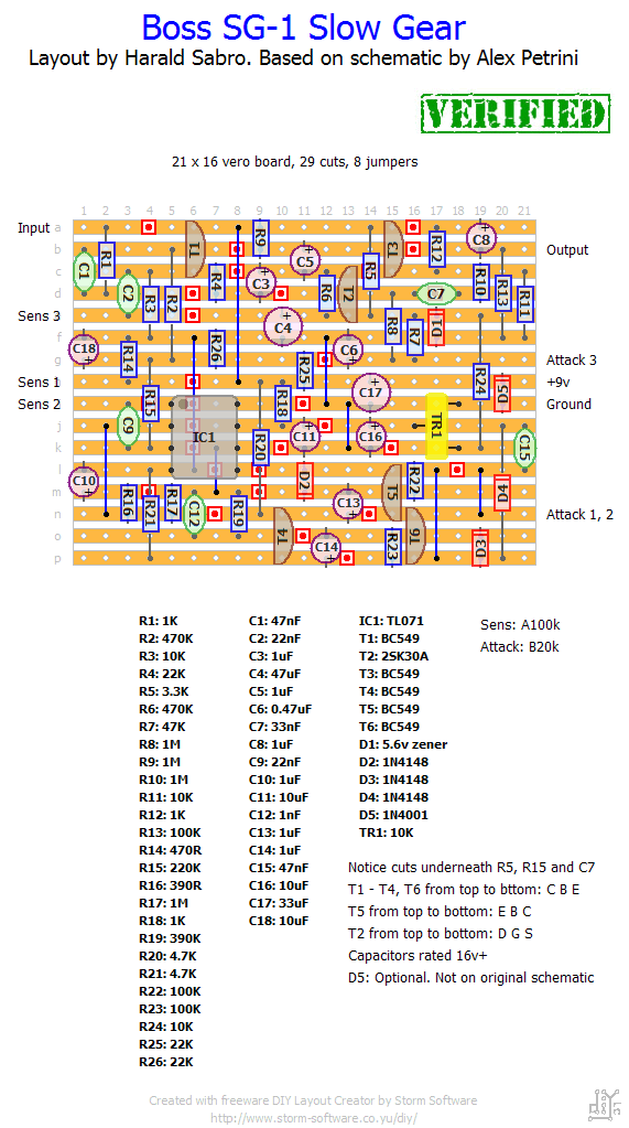
Update (16.12.14): Verified as working, thanks to Alec!
I’ve been meaning to do this one for a long time, and here it is. I no longer have any idea where I got the schematic, so no link, but it should be quite easy to locate I’m thinking. As always I imagine you’ll finish this long before I can even source the parts, so let us know 🙂


I haven’t tried this build yet, so no idea how to bias it.
1. Could it be done by ear (i.e. tweak until desired sound)?
2. A B25k is easier to find maybe? Or the A25k||100k probably works fine too. Just a guess.
Some questions still.
1. How do I bias the effect with TR1?
2. I do not have a B20K. Where can I get them or is a A25K with a 100K in parallel ok?
I do not know to be honest. Give it a try 🙂
It’s a 10k trim potentiometer.
Does it matter which BC546 I use BC546A or BC546B?
hello
can somebody tell what is TR1 in the layout??
thanx!
Hello
I’m new there. Just a thanks for this layout. It works and it’s better for me with C6 mod.
Thanks a lot for all your works
Happy you got it working, and thanks for the build suggestion!
I’m unfamiliar with the circuit, but from the looks of it I’d say C6 is part of the filtering for the reference voltage. I might be way off, though.
Built this last week, at first it’s not working and I was even didnt get the signal out from it, then I recheck my built and realize there’s little short in T3, fixed it and there’s signal came out, but no swell at all!
After some digging, someone said that you need to paralel the c6 with the 22uf. Did it, guess what? It swell… 😀
So for those who are building this, try to paralel c6 with the 22uf or just put bigger value if you dont want to add more component. But at least you have to make sure that there is actually signal out come from your circuit.
Last thing I want to ask, what is actually the c6 do??
-Cheers from indonesia
Toner,
Check out the “debugging” section for some tips. I would consider using an audio probe to narrow down where the signal “disappears”.
well i’ve build it with no change in every part, but i got no signal out from it,
checked the track
checked pin, polarity, value, everything…
but when engaged suddenly so silent no signal pass, no ground pass (i’ve try to touched tip and sleeve but got no noise at all, i try to touch pin on post-switch to it’s not humming) it’s like sucking signal and ground pre and post-effect, so strange.
Yes Harald. Its a weird beast though and needs a lot of string muting to get the best results. A tricky sort of trick pedal if you like. Not played the real deal but listening to demos it sounds right. If using the 2N5952 it will need some leg twisting because of the different pin out.
Nice, Alec! So I can call it verified?
Well it works! Spent ages debugging only to find my JFET’s were shorted (fleaced-bay). Will check first in future. A 2N5952 is a very decent sub for the FET but used the 2SK30A as I’d forked out for them (again). Good work Harald. Many thanks.
I haven’t built it yet, but I’m guessing it’s going to be component dependent or a bit of a pain to tune correctly.
Did anybody test it? built one some months ago and it didn’t work like it should.. Seemed like it has a gate and that you have to boost the signal or have high output..
Is this layout here better?
best regards
Marcel