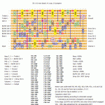
This one is supposed to give you some of that Dumble sound everyone and his dog is looking for. I’m not that happy with how the layout came out, I feel there’s a good bit of wasted space on the right-hand side, but the important thing in the end is how it sounds (no idea yet, let me know if you build it 😉 ).
This is going to be a bit of a challenge for a few reasons. You’ve got 7(!) pots and two extra switches with a lot of wiring to go with it, but the main challenge is going to to be tuning all those JFETs (check out the FAQ section for some info on this).
I’ve kept the component labeling identical to the original schematic with one exception; I changed the names of the JFETs and trim pots so that Q1 coincides with VR1 and so on. The FET/trimmer combination is also numbered according to where it comes in the signal path, so if you’re tuning this with e.g. an audio probe you start at Q1 and proceed from there in numerical order (remember that Q3 and Q4 can be taken out of the signal path based on the Drive switch).
Good luck! 🙂
Update (04.02.2013): Thanks to Graham for verifying this one 🙂


It should be correct according to the schematic (can also be found in dumble schematics, which is what this effect tries to emulate afaik).
Anyone please confirm that R17 = 47M, correct
Good feedback for future builders, steve. Thanks!
I decided to do some experimenting and put a PAB switch in the circuit. With the tone stack out of the circuit the 80/90 switch makes a considerable difference, interesting? Thinking about a mid boost also.
Cool, Steve 🙂 Keep building!
My thanks to Harald for the layout and many thanks to Graham for the wiring help! Got this together hoping for a OTS or RF tone, (still need to do some tweaking). Wiring is challenging but stuffing it all in a pedal will take some work. After troubleshooting some mis-placed cap leads all is working except I don’t hear a difference when toggling the 80/90 switch. Again Much thanks!!
Apparently, yes. You can probably get away with a substitution here.
Is R17 really 47M????
Thanks Harald, no need I found him!
Sorry Steve, unfortunately I can’t. Let’s hope he comes back.
Harald, is there any way you can drop a line to Graham? I noticed he has not been back to see my question for him?
Sorry Steve, your post was queued for spam filtering. I took the liberty of removing your second one.
Sounds like my kind of pedal, “actually sounds spot on to my ceriatone ods.” Graham, did you make this comment or was it tinkercreek? At any rate would whomever be willing to share a parts list and some gut shots with me? I would like to build one but would appreciate some help of this nature. I built an Umble but was never happy with the results even after changing jfets and bias. Never been in love with my Zendrive. Based on all the Ctone ODS clips i have heard maybe this pedal will be it.
Cool. Thanks for the info. I might compare some schematics and see if some more gain can be coaxed out of it….
Tinkercreek
Has got less drive than the zendrive with all j201 biased at 4.5 to 4.6v.must admit though it sounds very good but just needs a bit more edge to it for me.it actually sounds spot on to my ceriatone ods.
Graham
Is there not enough gain even in the drive channel? The Umble has loads of gain and that is even with my single coil pickups. That was always my issue with my Zendrive – wanted more gain, but the Umble has more than enough. And it has the same basic timbre, sound, feel, whatever you want to call it, as my Zendrive. Are the JFets biased correctly?
Would be nice to have a little more drive available,is there any way it could be done Harold?Has a beautiful clean tone and the right dumble feel just needs a tad more drive.
Graham
Nice one! Looking forward to building this. Just finished a ROG Umble. Sounds kinda like a Zen drive on steroids. This one looks like it may kick it up a notch or two.
Thanks
Very good news, Graham 🙂 Thanks for verifying!
Harold
After a few hours of debugging and getting nowhere i rebuilt it and found out i had missed out c18 and c20 ooops.consider it verified now.the wiring is a massive pain in the butt though.
Really nice overdrive that sounds very similar to my ceriatone ods as you would expect but at a much reduced volume 🙂
Not sure where to start on this one, Graham. I assume you’ve made all the additional connections listed on the left side of the layout? And since you’re getting a signal through all six JFETs I assume you’ve got the wiring right for the drive switch and all? Have you checked out the debug section I added recently? I would start with a visual inspection and then maybe try to isolate the problem with an audio probe. But nobody has built and verified this yet so there might just be a mistake on either the layout or the schematic I based it on.
Hope you’re able to sort it.
Thanks Harald,got it working but no gain and the level and drive aint doing anything and volume is low.all biased up to 4.5v and signal is getting through all 6 j201.mmmm
Graham, check out the FAQ section. I’ve added illustrations on lug numbering etc.
Going to have a try at this and just need to check how you are numbering the 3dpdt and the dpdt?
Regards
You are a Star !