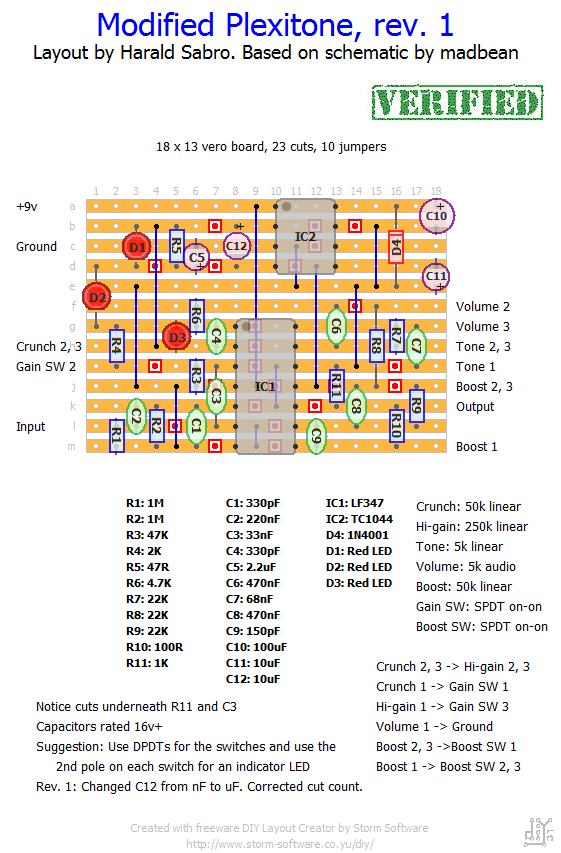
Here’s a vero layout of the Carl Martin Plexitone based on madbean’s schematic incorporating the suggested mods to tame it somewhat. I haven’t tried this one myself. Let me know if you do before I get around to it.
Update (05.09.2011): Fixed a couple of minor errors (electrolytic was mislabeled as nF and the cut count is now correct). Still haven’t verified the layout.
Update (25.09.2011): Built this circuit tonight. This one is now verified working 🙂


Hi, Harald.first of all,sorry for my poor English,from Japan.
It was the second time that I made guitar effector.
Your layout really helped me out.
By the way,Can I get this circuit diagram? I want to arrange your great layout.
Hey Harald,
Thank you. I’ve finally build one. Its perfect. I wanna ask: is there a layout for 12v dc version? What changes should i do?
Regars, Louis.
Hi Harald H,
Lots of questions and a bit hard to give an answer to them all. Check out the different sections here to get some of the answer (switch numbering, wiring), and start digging into the forums I have linked to on the right-hand side.
Hi there,
that stuff is great work. But its diffcult for me to read. I’m able to solder but i don’t check what’s going up in such a circuit. And i don’t know what is meant by Gain SW1 and Gain SW 3. Is it much work to the connected pots and switches in the schematic? I own a original Carl Martin Plexitone and have a “select”-switch, wich i don’t find in the schematic.
I find the original not very usable. So i want to change some stuff (when i have learned enough about electronics ;-). So i think it would be a better solution to have a separate volume and tone pot for the “high gain” channel. Do you agree? Is that possible?
Thank you all and greets from Cologne
Harald H.
Happy building, Dale 😉
AHHA.
Proving once again that there IS such a thing as a stupid question…I actually looked at the IC #’s then got in my 14 leg IC bin and guess what I found?? One LF347 chip. Never mind….happy building all!!
dale
Hi all.
I have LM301,308,311,386,358–LF353’s….would any of those (or anything not listed!) sub for the LF347??
dale
The LEDs should have a flat side indicating negative/cathode. In any case, for this particular layout all the LEDs have the negative/cathode facing downwards.
hi, which side of theled is the plus en which one is the min in this schematic?
thanks!
You’re mainly interested in the voltage drop of the LED and not it’s size, so I’d go for 3mm red diffused LEDs. The 3mm ones work just as well as the 5mm ones for this, and they take up a lot less space on the circuit. If you want to experiment you can try other colors, which have different voltage drops and consequently will let a different amount of signal pass before clipping.
hi harold,
Which type of led should I buy for this one (http://www.newtone-online.nl/catalog/index.php?cPath=38_39).
regards,
Lars
Great! Thanks!
Hi Johann,
I think I have a few other utility circuits lying around, one of them being a +9v -> +18v converter that you might be able to use. Let me see if I can upload them.
Hi Harald, first of all, thanks for this load of layouts!
I’ve been looking around about possibilities using 18VDC in this pedal. Initially, I thought about using the general TC7660s charge pump layout and feed the output into the voltage inverter of the plexitone. But I can’t find a proper IC that handles the 18VDC. Do you have any recommendations?
The other possibility would be to incorporate the symmetrical voltage multiplier by analogguru or the voltage doubler/divider circuit of the Plexituna layout done by bucksears (on freestompboxes.org). Since I’m not really expert in designing layouts, would you probably modify the stripboard layout, for internal conversion to 18VDC, please?
Cheers, Johann
By “third switch” do you mean the “Boost” switch? If so it’s quite easy, really.
You want a DPDT on-on switch (an SPDT on-on will suffice if you don’t want to include a “Boost LED”). Now wire switch lug #1 to lugs #2 and #3 on the “Boost” pot. Next connect switch lugs #2 and #3 together and also to lug #1 on the “Boost” pot. If you want a “Boost LED” you also need to connect switch lug #5 to ground and the LED cathode (-) to switch lug #6 (and the LED anode (+) to +9v via a resistor of approx. 4k7).
Hope that made sense, and good luck 🙂
I have all the parta ready. This is my first pedal, can anyone help with how I wire the third witch like on the Boneyard?
Now that it’s build, how does this sound? 😀
I’ve built your plexidrive, is this one very different? Thanks! 🙂
Thanks Harald…it was clear the connection to both lugs…but it wasn’t clear the “crunch 2,3 —> hi gain 2,3” writing…
Or better, it was the first time that i’ve found it. 🙂
Anyway…thanks a lot Harald…for your time and your site.
Thanks!
I wasn’t able to respond quick enough. Glad to hear you’ve solved it.
And you probably figured it out, but “crunch 2, 3” means “this point on the vero board needs to connect to both lugs #2 and #3 on the crunch pot”. Wire it to #2 and put a jumper between #2 and #3 (you can actually skip #3 altogether as long as you’ve got #2 connected).
LOL!!!
I’ve find the problem…a bad solder point on a jumper!
Now the pedal works great, even if there are noises at max level of crunch…i will try to optimize the ground schematic…
Thanks a lot!
…and also, just to understand if i’ve done in right way…
you say: crunch 2,3 —> higain 2,3
it means that pin 2 of crunch has to go to pin 2 of higain, and pin 3 of crunch in pin 3 of higain…right?
Help please!
Thanks!
Hi Harald…i’ve made this layout and now i’ve a big POOP when i switch on the effect, and after the poop the silence…
I’ve seen that the circuit is hot…
Do you have any suggest for this problem?
Thanks a lot!
Hi,
i build this with a 7660S and it works like a charm! To my ears this circuit had too much fizzy top end, so I changes C9 to 4n7 and wooooow! The fizzy highs are almost gone and there are a bit more high mids, which makes this pedal so much more usable.
Using a 250K *audio* higainpot makes the range of wonderful sounds even wider….
Hi Harris. Try the MAX1044, I know smallbear has it. Or you can use the 7660 as long as you get a variant with the ‘S’ suffix, which is a bit cheaper.
just another one question.. cant find the TC1044 IC on my local dealer not even at Banzaimusic.com
any alternative suggestion?
thanks again
Yes, you can wire this as true bypass. Have a look at the wiring illustrations in the “schematics & drawings” page. Hope that’s what you’re looking for.
awesome work dude i just found your site and i’m stunned. i’m new to diy… i build pedals on my free time and half my pedals are made by me. i got a question on the plexitone. is this tbp? and is it possible to link the wiring cause i’m sure i’m going to ruin it in that part. thanks again man this is heanen 😛
Great layouts Harald! Thanks… I intend on using vero board to build this circuit. I currently have it on a breadboard from the schematic found over at MadBeanPedals. This pedal sounds amazing. Great Marshall type tones. It does AC/DC and Blazing 80’s hair music great, as well as lower gain stuff like ZZTop and Led Zeppelin. Overall, great pedal, so I highly recommend building one if you are searching for that great “Marshall in a box” sound.
Seems nice from the only video I’ve found! BTW, to link the 2 other switches (boost and hi-gain) with a led, how the 3pdt should be wired? Still don’t understand completely the mechanism of it 🙂 shame on me! XD (btw I’m a medicine student.. I don’t have any “formation” on this stuff, I just can build them!)
I have no idea what it sounds like, but I guess a quick search on youtube would show some demonstrations? From the name I’m guessing it’ll sound Marshall’y.
How it should sound? 🙂