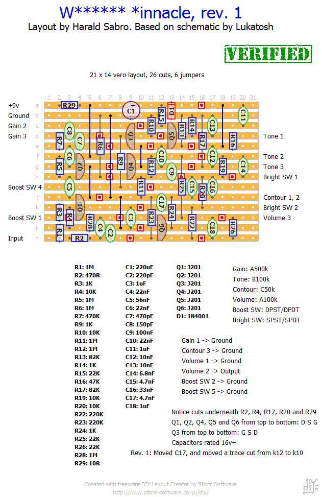
This looks very similar to the BSiaB2, so I’m guessing it’s supposed to sound like a Marshall. Enjoy.
Update (31.01.2013): Revision 1; fixed a mistake on the layout where C17 was misplaced. Thanks to Pierre for spotting this.
Update (02.02.2013): Now verified, thanks to Kenneth and Pierre. If you’re having trouble matching JFETs for this one try lowering the drain resistors on Q5 and Q6 to 15k (R15 and R25).


Unless I misunderstand you, where R5 and R6 meet should probably read ~4.5V (or half the supplied voltage) since it’s a voltage divider/reference voltage.
Is your battery/power supply only supplying +6V? If not you might have a mistake somewhere (refer to debuging section for some help).
Hi
Harold
to the heads of R5 and R6 is the voltage of 2.9/3.0 Volts . Is it correct?
Since all of the W*** effects rely on fixed drain resistors and matched FETs, that’s where I would look first. Measure the voltages on your transistors; the drain voltages of each one should read around +4.5V +/- for there to be any sound at all. If not biased correctly you either have to swap out the drain resistors for ones that will give the correct bias, or you have to search and find FETs that will work well with the resistor at hand. You can read more about this in the FAQ section.
Hi!
Built mine month ago. No signal att all…
Rebuilt it and still no signal.
Any idea where to look?
Best regards
Dario
That’s a fairly common problem with high gain effects. Check out the FAQ section on squealing effects for some ideas where to go.
I recently built this pedal and I’m getting a high pitched squeal from the gain pot. I have checked for bridges, component placement, soldering joints, and wire placement. I have no idea where this noise could be coming from. Do you have any suggestions of what it might be?
Thanks,
Jasmine
Fernando, you could try adding a capacitor in parallel with R9, similar to R3/C3.
What i need to do (if it’s possible) for pushing up (volume or gain) a little bit
the boost mode.
I think the boost mode has’t a very noticeable diference of the normal effect.
Good to hear 🙂
Hi Harald.
I found that I had R19 not stretched out enough. Works great.
details details.
Afraid I can’t be of much help here, Dale. I’d refer you to the debug section for some tips, but sounds like you already covered most of this.
Hi Fernando,
You wire the boost switch as normal using two of the three poles on the 3PDT. The last pole is used to toggle a LED on and off.
– Wire from +9V to LED resistor (1k-10k of your choice).
– Wire from other end of LED resistor to LED anode (+).
– LED cathode (-) to 3PDT lug #7.
– 3PDT lug #8 to ground.
Hi Harald,
I built the W****** *innacle and it works fine except….the tone control has no effect, and when I move the Bright switch up, everything goes dead.
Again, the sound is very good, the distortion is a wide range but the bright/tone thing is strange. I switched the SPST bright switch for a new one with no affect. I checked every value, solder joint, trace and found nothing. Any help you can give would be greatly appreciated.
Dale
Hi Harald
I’ ve just completed the pinnacle vero layout .
For the final built i want a 3pdt footswitch with a led for the boost mode
I would like help for this (wiring).
Thanks!
Great to hear you got it working, Pierre 🙂 I’m guessing you would eventually have found a couple of JFETs that would match well if you had tested enough of them, but adjusting the drain resistors is good. I’ll keep the layout as-is since this matches the actual units, but I’ll add a suggestion on lowering the drain resistors. Thanks for verifying 🙂
As I did add 1 strip below and 1 strip down the vero, I found some place to put some 22k trim pots. Tuned Q5 to 3.5v and Q6 to 3.86v and…. YESSSS that ROCKS! =)
Thank you so much for your advice Harald. Felt uncomfortable with changing something on this layout on the first time but that was definetly the thing to do. As the guys from tagboard reported the same issues, could I suggest this change on your layout?
I found this here:
http://tagboardeffects.blogspot.fr/2012/07/wampler-pinnacle.html
“Just finished this one. I had some issues with getting the correct voltage values on Q5 & Q6. I found a schematic with 15k resistor to Drain (instead of 22k). I ended up with two 22k in parallel (=11k) to Drain on both and that did the trick :)”
Gonna try this!
Happy to make myself usefull!
According to my limited skills in english and electronic I’m not sure to get what you say about matching Jfets in these FAQ. I’ve understood that I should read a value between 4.5v and 5v on each drain. Actually I’ve got something around 0.7v on Q5 and Q6. Seems to be the problem. I’ve changed them (and the others) but it stays the same. Again, if I understand the matching theory, I should try different J201’s until getting the right value?
I did not mentionned that on my first reply but the symptom got worse after my first try.
Hi Pierre,
I looked it over and C17 is clearly a mistake on my part. I’ve updated the layout (had to move a trace cut to make room for C17 at it’s new location).
You’re right about C4 and R28 not being present on the schematic you linked, but this shouldn’t make any functional difference I think (it’s a high pass filter that cuts everything below ~10Hz I believe).
If you’re still having problems you may have to match Q5 and Q6, i.e. find ones that operate at the right drain voltage (check the FAQ on matching JFETs).
Hope this helps, and sorry for the layout mistake.
Hi Harald,
Just built this one but it doesn’t work properly: kind of delayed volume swell and trebly sound. I’ve checked it severall times but didn’t find any mistake. So i searched for a schematic and found this one :
http://3.bp.blogspot.com/-EHqlC7DbtvQ/T0zbtF_y_YI/AAAAAAAAA_c/6Qj-B-e2pOA/s1600/pinnacle+2.jpg
On your layout C17 is connected to C16 while it is grounded in this schematic. Tried it but it didn’t fix anything. I’m confused.
I’ve also noticed that the 470R resistor is straightly conected to the gate of Q1 while it is through a 22n capacitor (C4) plus a grounded 1M resistor (R28). I guess it’s just a filter that has been removed in the supposedly second version of the pinnacle so didn’t try anything there.
Should I incriminate the j201’s or the capacitors? Have you heard about such problems?
Hi Danto,
the A pots are log/audio, the B pots are linear and the C pots are reverse-/anti- log/audio.
Hi, i’m gonna build this pedal, thanks for the grat work!
I only have one doubt. Since i’m making the order now, i wanted to know how you named the pot; i mean:
A=lin
B=log
C=???
I’m a bit anxious, since it’s not verified, but at least i’m making myself useful..