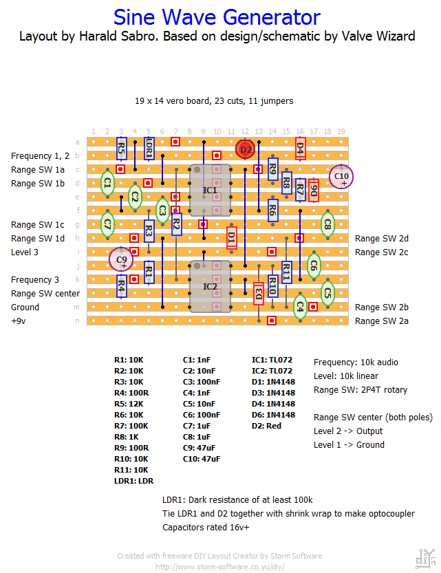
Here’s a layout for a useful, but different kind of circuit. The Valve Wizard has several cool designs/projects on his site and this one should be a great testing tool you can use to generate a test input signal with. I’m building this one 🙂
Update (09.09.2012): Built this a while ago and couldn’t make it work at all. Bummer…
But then I fooled around a bit and figured out that if I disconnected the 2nd pole of the rotary from the circuit everything sprang to life and it worked as expected. Now this would effectively remove C4, C5, C6 and C8 from the circuit altogether, and I’m not sure how this works. I.e. I’m reluctant to call this one verified, but if you do build it and can’t make it work try connecting only “Range SW 1 center” and leave “Range SW 2 center” disconnected. Wish I knew more on the theory at work here…


